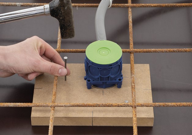
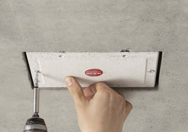
1. Mark desired position for luminaire on formwork with a cross. Use this to align formboard (230x150x25mm) and nail formboard down as shown in picture. Fix mounting capsule for concrete as shown in picture in the place you have marked and connect empty conduit.
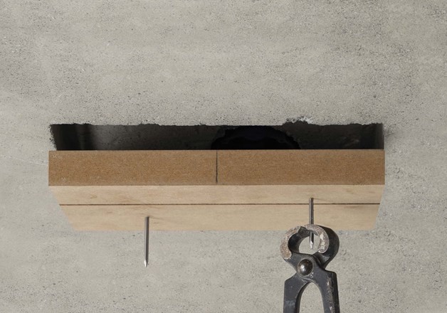
2. When formwork is stripped, formboard will be removed from ceiling. If necessary, use a tool to do so.
3. Take module from packaging. Take mounting flaps and insert into lateral cutouts so that flaps extend into module. Mounting flaps must be inserted as far as they will go and must not stick out from module.
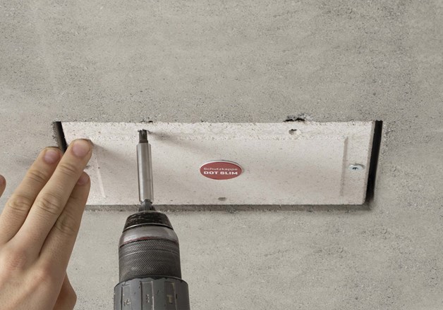
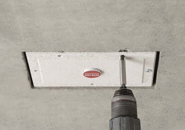
4. Adjust module in opening and use a 5mm drill to drill the holes needed for fixing the module with.
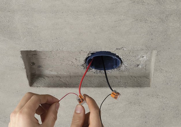
5. Take module back out of opening and establish module’s electrical connection. Make sure to observe serial cabling (series connection) and maximum current feed.
6. Carefully fix the module in opening with countersunk screw. Make sure module is fastened securely and flush with ceiling surface.
7. Carry out continuity test to check if electric circuit is closed. Then remove wire link.
CAUTION: Coordinate the filler thickness desired with site supervision or the tradesmen involved.
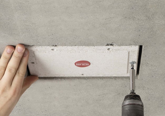
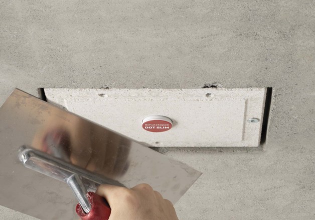
8. Adjust filler edge according to desired filler thickness (0-6mm) by evenly aligning the three adjusting screws.
9. Insert the red protective cover and then fill the gaps neatly with the addition of a fabric tape.
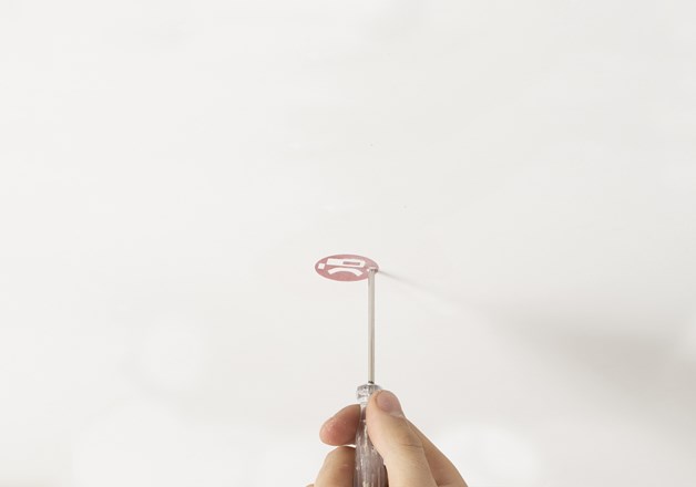
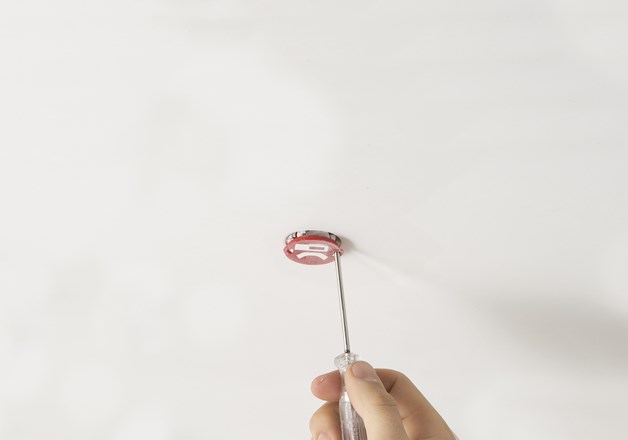
10. Carefully sand over red protective cover until it is entirely visible. Remove it using a slotted screwdriver. Imprecisions have to be reworked by hand.
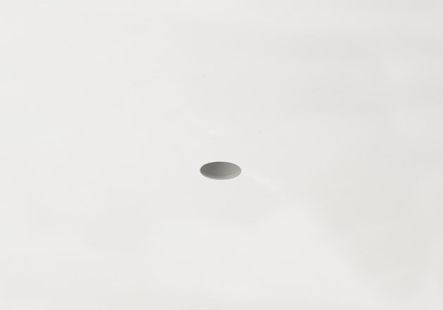
11. Prime and paint module and filler ring with ceiling paint. Make sure that no primer or paint gets into the fixture into the LED insert.
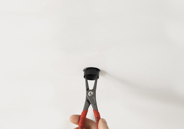
12. Put desired LED insert flush into LED mounting and turn clockwise by approx. 90° until it sits securely. You may use the DOT 28 System mounting pliers to do so. CAUTION: HOT PLUG! Every luminaire ist tested in live operation before shipping.
Installation DOT SLIM drywall
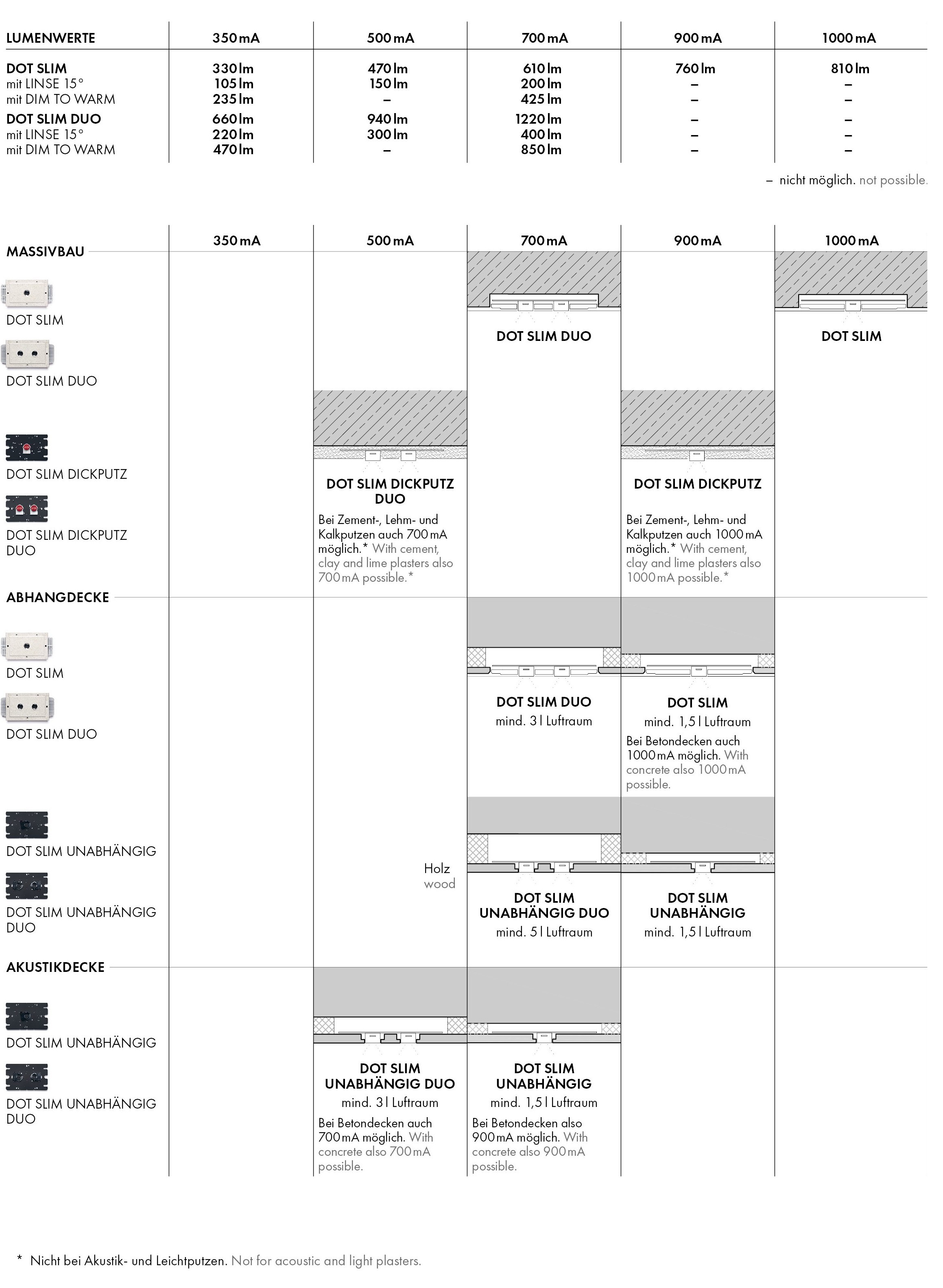
DOT SLIM: 900mA (760lm), installation depth: 40mm, min. 1,5l airspace (current feed of 1000mA possible for concrete ceilings, air space can be eliminated)
1. Make cutout of 220x140mm in plasterboard. Clean and chamfer the edge of the cutout as customary in drywall construction. Make sure that required installation depth of 40mm and required airspace are provided.
2. Take module from packaging. Take the mounting flaps, turn them around and insert them, sticking out, into the cutouts at the short side of the module.
3. Establish the electrical connection of the DOT SLIM installation module. Observe serial cabling (series connection) and maximum current feed.
4. Fit installation module into ceiling cutout using mounting aid.
5. Screw module unto ceiling from below through mounting flaps. The mounting aid included in the delivery may be helpful for keeping the module flush with the ceiling’s lower edge.
6. Carry out continuity test to check if electric circuit is closed. Then remove wire link.
CAUTION: Coordinate the filler thickness desired with site supervision or the tradesmen involved.
7. Adjust filler edge according to desired filler
thickness (0-6mm). Adjust the three screws evenly in little
steps. If one set screw is adjusted more than the other, the
filler edge will not be parallel to the ceiling surface. Important! The filler edge must be set parallel to the ceiling surface.
8. Insert the red protective cover.
9. Plaster ceiling in thickness of your choice.
10. Carefully sand over red protective cover until it is entirely visible. Remove it using a slotted screwdriver. Imprecisions have to be reworked by hand.
11. Prime and paint module and filler ring with ceiling paint. Make sure that no primer or paint gets into the fixture into the LED insert.
12. Disconnect modules from electric circuit. Put desired LED insert flush into LED mounting and, using mounting pliers, turn clockwise by approx. 90 ° as far as it will go. CAUTION: DANGER OF HOT PLUG! Every luminaire ist tested in live operation before shipping.
Installation DOT SLIM THICK PLASTER
DOT SLIM THICK PLASTER: 900mA (760lm), if lime, plaster, clay or cemet is used,
current feed can be increased to 1000mA (810lm)
DOT SLIM THICK PLASTER DUO: 700mA (1220lm), ATTENTION: for insulating and acoustic plaster: max. current feed of 500mA
1.
Depending on the plaster thickness, various preparations must be made when installing the module:
25-30mm Putzauftrag: Plaster thickness of 25 to 30 mm:
Module requires plaster thickness of 25 to 30 mm for standard
installation. -25mm Putzauftrag: Plaster thickness < 25 mm: If plaster
thickness is less than 25mm, an insert (230x150mm) has to be
put in place during concrete work already in order to make up for
lacking plaster thickness. +30mm Putzauftrag: Plaster thickness > 30mm:
If plaster thickness exceeds 30mm, a false edge has to be
established under the module in order to make up for excessive
plaster thickness.
2. Mark desired position for luminaire on raw ceiling with a cross.
3. Align module with marking and use a 5mm drill to drill the holes
needed for fixing the module with concrete screws. If necessary, adjust to desired
plaster thickness using the adjusting screws.
4. Carefully fix module on raw ceiling using the concrete screws
enclosed in your delivery and make sure it is fastened securely. Attention: Cooling plate must not be deformed!
5. Establish module’s electrical connection. Make sure to observe
serial cabling (series connection) and maximum current feed.
Terminal clamp : cable cross section max. 1,5 mm².
6. Carry out continuity test to check if electric circuit is closed. Then remove wire link.
7. Insert the red protective cover.
8. Plaster ceiling as desired. Use large-scale plaster fabric when plastering over luminaire module.
9. Make sure that after plastering, entire circle of red protective cover is cleared and visible. Clean any plaster residues from protective cover.
10. Remove the protective cover and prime and paint module and
filler ring with ceiling paint. Make sure that no primer or paint gets into the fixture into the LED insert.
11. Put desired LED insert flush into LED mounting and turn clockwise by approx. 90° until it sits securely. You may use the DOT 28 System mounting pliers to do so. CAUTION: HOT PLUG! Every luminaire ist tested in live operation before shipping.
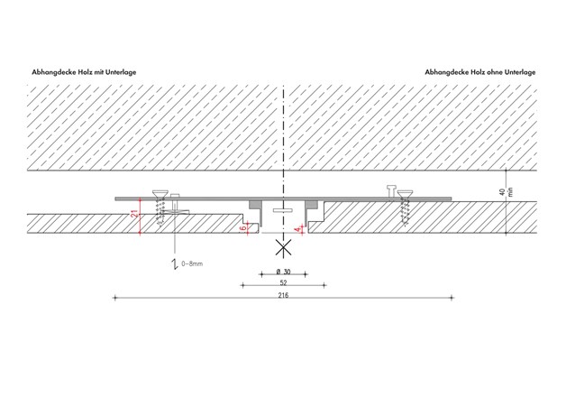
Installation DOT SLIM INDEPENDENT
DOT SLIM INDEPENDENT: 900mA (760lm), min. 1,5l airspace
DOT SLIM INDEPENDENT DUO: 700mA (1220lm), min. 3l airspace
1.
Cut recess for LED mount into desired board according to drawing.
2.
On back of module, set desired board thickness using the three setting screws. Observe fixed measurements, shown in red in drawing.
3. Mount module on board form behind. To do so, use holes next to setting screws. Attention: Cooling plate must not be deformed!
4.
Establish module’s electrical connection. Make sure to observe serial cabling (series connection) and maximum current feed.
5.
Carry out continuity test to check if electric circuit is closed. Then remove wire link.
CAUTION: Airspace and maximum current feed must be complied with.
6.
Put desired LED insert flush into LED mounting and turn
clockwise by approx. 90° until it sits securely. You may use the
DOT 28 System mounting pliers to do so. CAUTION: HOT PLUG! Every luminaire ist tested in live operation before shipping.
DOT SLIM - LENS 15°:
- DOT SLIM with LENS 20° can only be used with the built-in modules featuring a
black anodized cooling plate.
(Item No. 317101, 317106, 317301, 317306, 317701, 317706)
- Depending on the installation situation, DOT SLIM with LENS 20° can be powered with a maximum of 700mA. (see table - max. current)
- DOT SLIM with LENS 20° in the built-in module DOT SLIM INDEPENDENT DUO in wood (Item No. 317706), must only be installed in an airspce with a minimum of 5dm³.
DOT SLIM - DIM TO WARM:
- DOT SLIM with DIM TO WARM can be powered with either 350mA or 700mA depending on the installation situation. (see table max. current) The dimming curve is adjusted to this.
- DOT SLIM with DIM TO WARM in the built-in module DOT SLIM INDEPENDENT DUO in wood (Item No. 317706), must only be installed in an airspce with a minimum of 5dm³.
Due to power input, the drivers DA-PU 25W 350mA (Item No. 299223) and DA-PU 40W 700mA (Item No. 299247) may only be operated with a maximum of 3 luminaires in series when DIM TO WARM is used. Driver DA-PU 60W 700mA (Item No. 299267) can be operated with a maximum of 5 luminaires.
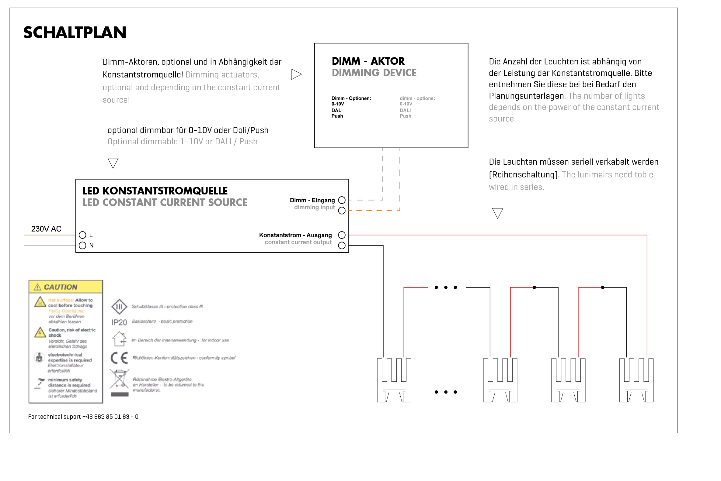
ELECTRICAL INSTALLATION:
All electrical installations and maintenance work must be carried out by an
authorised electrician according to local safety regulations.
All luminaires are tested live working before packaging.
Please observe the circuit diagram enclosed.
CAUTION: NO WARRANTY IN CASE OF HOT PLUG!
DO NOT CONNECT, LOCK OR REPLACE LUMINAIRES UNDER VOLTAGE!
For mounting and dismounting the luminaire the led-driver has to be disconnected from the supply voltage for at least 10-15 seconds! HOT PLUG causes direct damage to the LED, which is not covered by warranty.