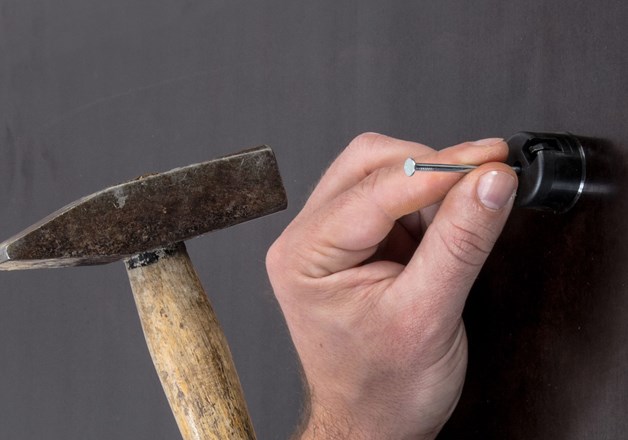
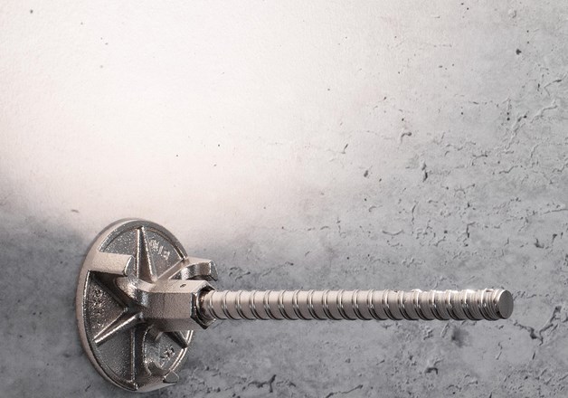
1. Use the supplied galvanized nail to nail formwork plug onto formwork.
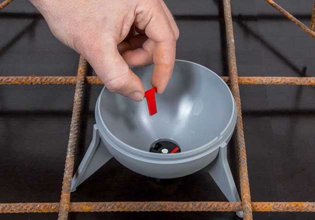
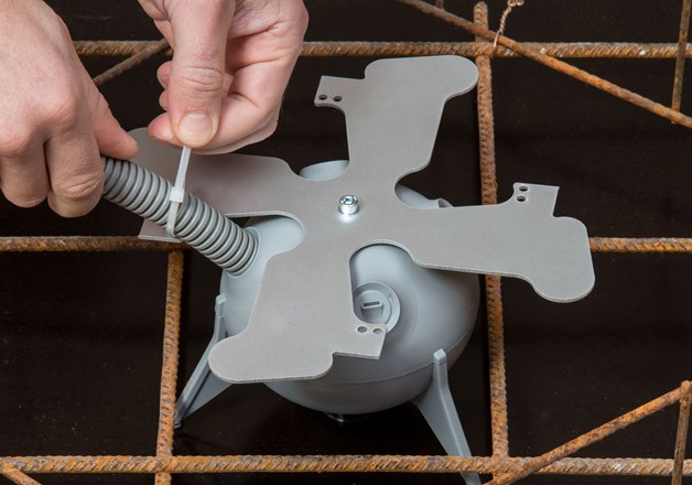
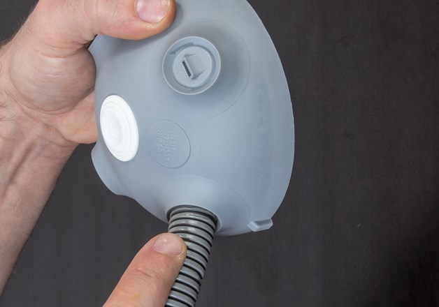
2. Place lower part of the capsule onto formwork plug and push until it
locks firmly into place. Insert both locking pins into the upper slots in the formwork plug.
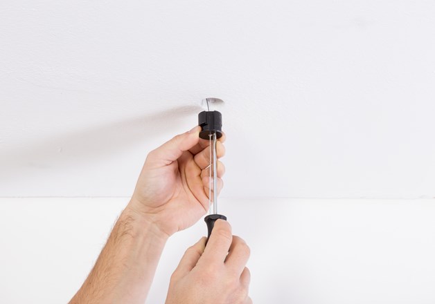
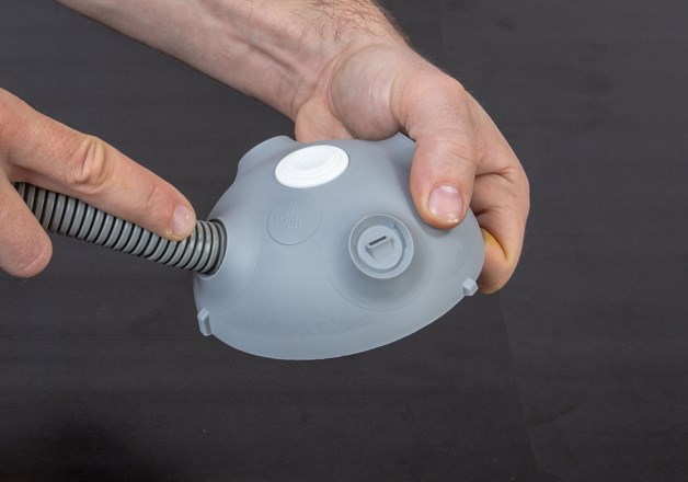
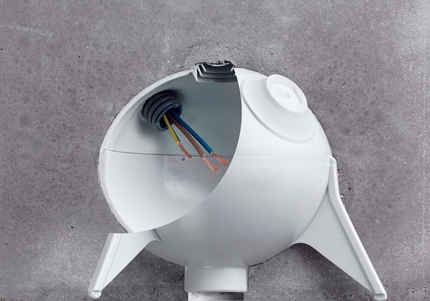
3. Use screwdriver to clear the openings needed for empty conduits in the lid and clean them. Press empty conduits into openings until it they are fastened (about two or three corrugations). Now firmly push capsule lid onto lower part and lock it into place.
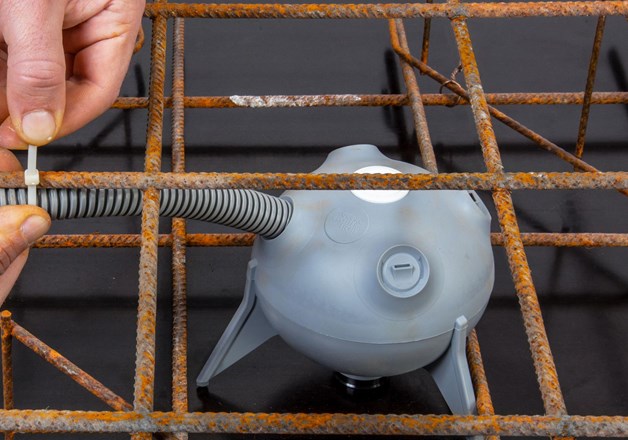
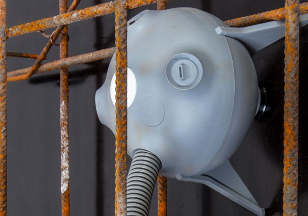
4. Securely fasten empty conduit to rebar to prevent it from loosening through concrete or concrete vibrator.
For element ceilings/filigree ceilings please use our formwork plug (Item No. 208030) for gluing.
5. (OPTION) When using capsule cover with added cooling surface, fasten empty conduit directly onto added cooling surface.
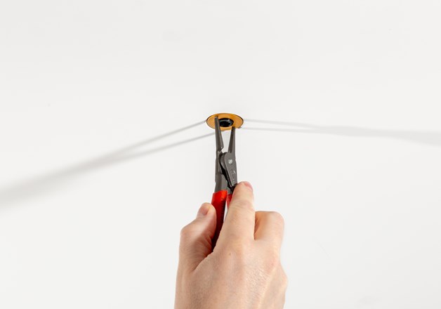
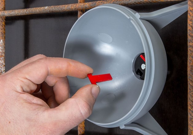
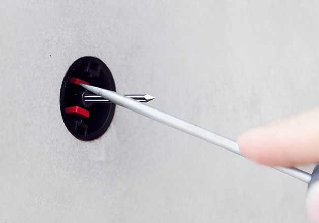
6. After stripping formwork, clamping mechanism has to be unlocked by pushing locking pins into cavity of the capsule with a screwdriver. Now remove formwork plug by pulling the nail with pliers. Remove locking pins and clean capsule, if necessary, for further use with bayonet mechanism.
CAUTION: Under extreme weather or environmental conditions (heat, high humidity), lid of capsule may open more easily when the concrete is vibrated. If such conditions are present, secure lid to lower part of capsule using fabric tape or other means (e.g. cable ties).
In the case of exposed concrete ceilings, small hairline cracks may occur due to installation casings or insert components. These do not constitute a reason for complaint.
CAUTION: If the DOT 28 POWER can not be mounted without resistance the cooling surface might has been set in concrete at an angle. Do not apply pressure on the DOT 28 POWER and do not disassemble the cooling mandrel! Use the adjustment iron (Item No. 208901) for the subsequent adjustment of the cooling mandrel! The subsequent adjustment is executed by hand or by using a hammer.
1. Use the supplied nail to nail formwork plug onto formwork.
2. Place lower part of the capsule with the marking UP (=direction of light) on the shuttering plug until it locks into place. Insert both locking pins into the upper slots in the formwork plug.
3. Use screwdriver to clear the openings needed for empty conduits in the lid and clean them. Press empty conduits into openings until it they are fastened (about two or three corrugations). Now firmly push capsule lid onto lower part and lock it into place.
4. Securely fasten empty conduit to rebar to prevent it from loosening through concrete or concrete vibrator.
5. Pay particular attention to the capsule when concreting. CAUTION! Protect them from falling concrete or shaking!
6. After stripping formwork, clamping mechanism has to be unlocked by pushing locking pins into cavity of the capsule with a screwdriver. Now remove formwork plug by pulling the nail with pliers. Remove locking pins and clean capsule, if necessary, for further use with bayonet mechanism.
7. For the electrical connection of the ARCHI-TEC please see to the relevant instalation instructions.
1. Use the supplied galvanized nail to nail formwork plug onto formwork.
2. Place lower part of the capsule onto formwork plug and push until it
locks firmly into place. Insert both locking pins into the upper slots in the formwork plug.
For element ceilings/filigree ceilings please use our formwork plug (Item No. 208030) for gluing.
3. Use screwdriver to clear the openings needed for empty conduits in the lid and clean them. Press empty conduits into openings until it they are fastened (about two or three corrugations). Now firmly push capsule lid onto lower part and
lock it into place.
4. Securely fasten empty conduit to rebar to prevent it from loosening through concrete or concrete vibrator.
5. (OPTION) When using capsule cover with added cooling surface,
fasten empty conduit directly onto added cooling surface.
6. After stripping formwork, clamping mechanism has to be unlocked by pushing locking pins into cavity of the capsule with a screwdriver. Now remove formwork plug by pulling nail with pliers. Remove locking pins and clean capsule, if necessary, for
further use with bayonet mechanism.
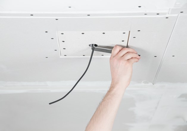
7. After stripping formwork and removing formwork plug, use installation tool to adjust filler ring to desired plaster thickness (0-15mm).
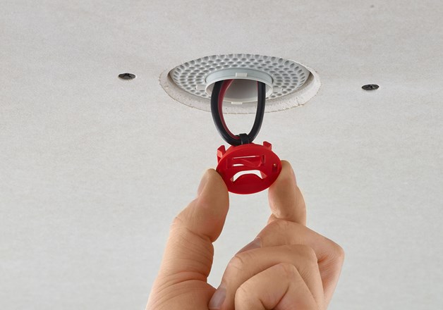
8. Removing mounting ring with pliers will expose the plaster claws. Make sure plaster claws do not stick out to the front. Claws must be completely covered by plaster.
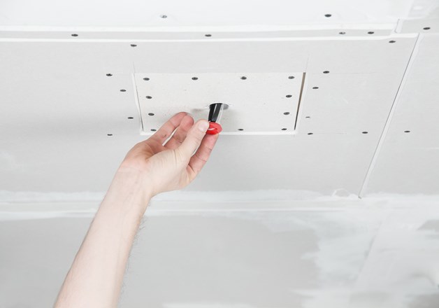
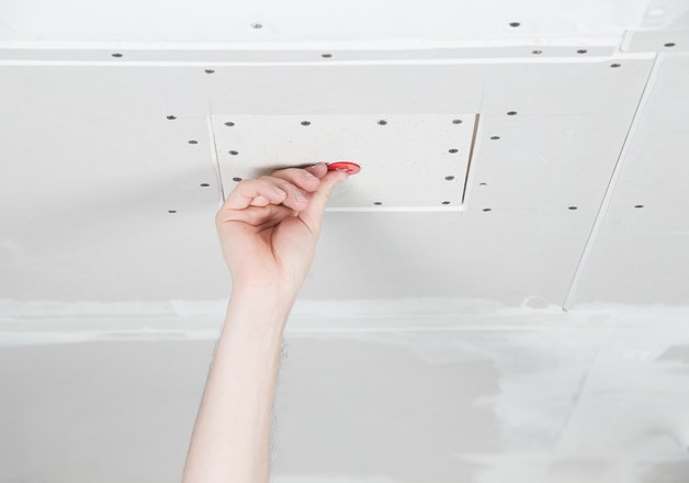
9. Fasten supply line to protective cover and use the cover to close opening. Make sure plaster claws have a solid grip in the plaster.
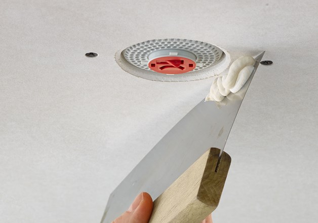
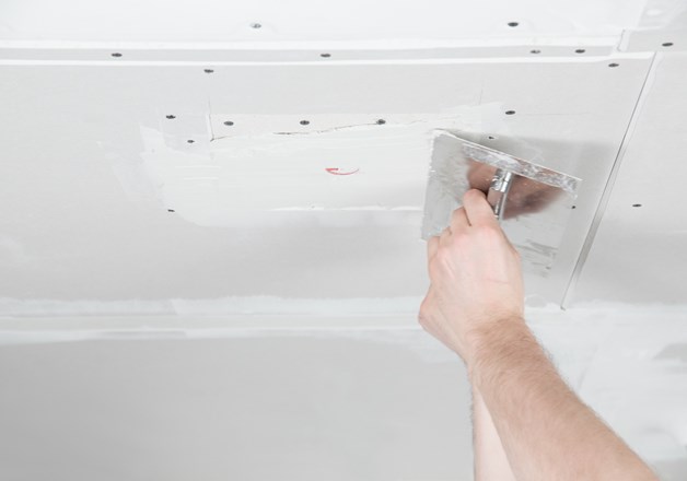
10. Plaster ceiling in thickness of your choice.
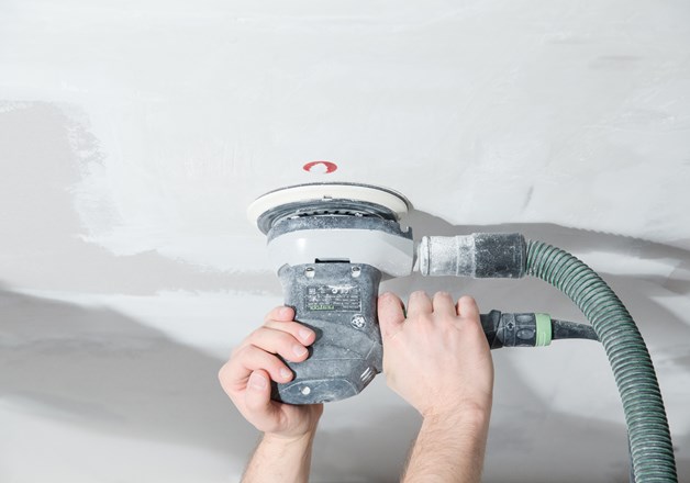
11. Carefully sand protective cover until it is entirely visible.
CAUTION: Do n ot abrade protective cover or the plaster claws will be exposed.
After sanding, remove protective cover and pull cable to the front. Imprecisions have to be reworked by hand.
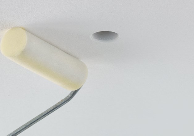
12. Prime and paint module and filler ring with ceiling paint.
CAUTION: Please check with your plasterer if you want to use coarse, loam, or acoustic plaster.
Under extreme weather or environmental conditions (heat, high humidity), lid of capsule may open more easily when the concrete is vibrated. If such conditions are present, secure lid to lower part of capsule using fabric tape or other means (e.g. cable ties).
CAUTION: If the DOT 28 POWER can not be mounted without resistance the cooling surface might has been set in concrete at an angle. Do not apply pressure on the DOT 28 POWER and do not disassemble the cooling mandrel!
Use the adjustment iron 208901 for the subsequent adjustment of the cooling mandrel!
The subsequent adjustment is executed by hand or by using a hammer.
Installation DOT 28 plaster module
INSTALLATION DEPTH: depending on module
LOAD CAPACITY: max. 10kg
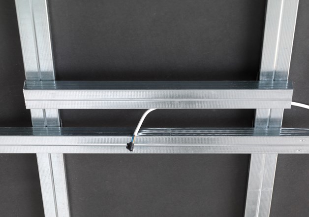
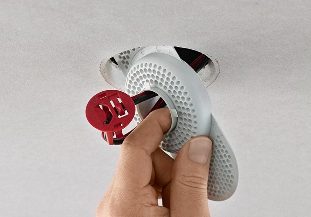
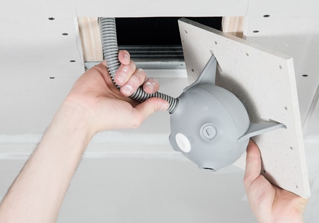
1. Prepare substructure for screwing module into drywall ceiling.
2. Feed cable through opening in plaster module.
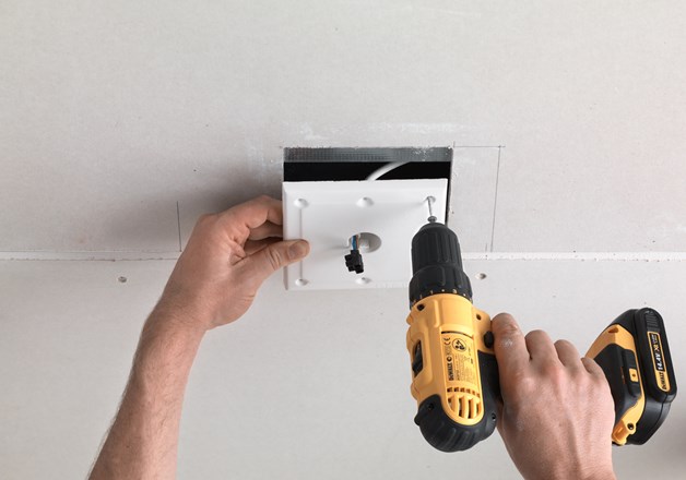
3. Carefully screw plaster module into prepared opening.
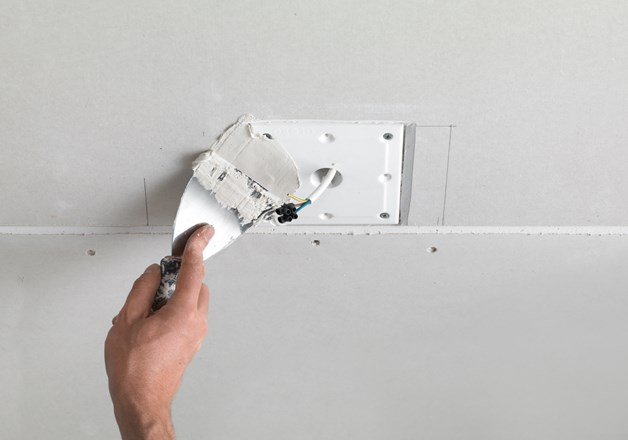
4. Adding fabric tape, fill the joints. Make sure to plaster the joints only and not the entire module.
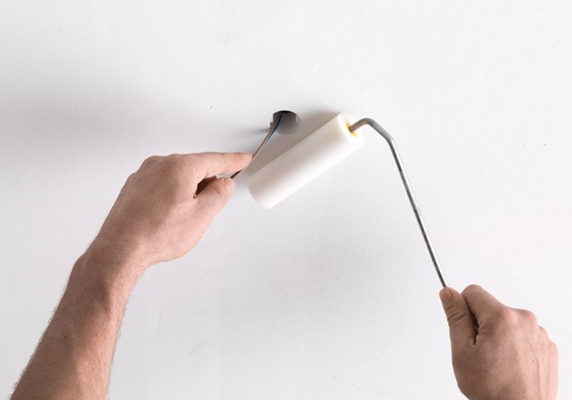
Prime and paint the plaster module with the ceiling paint. Plaster modules are not suitable for coarse plaster!
CAUTION: Please check with your plasterer if you want to use coarse, loam, or acoustic plaster.
Plaster modules are brittle and may break easily.
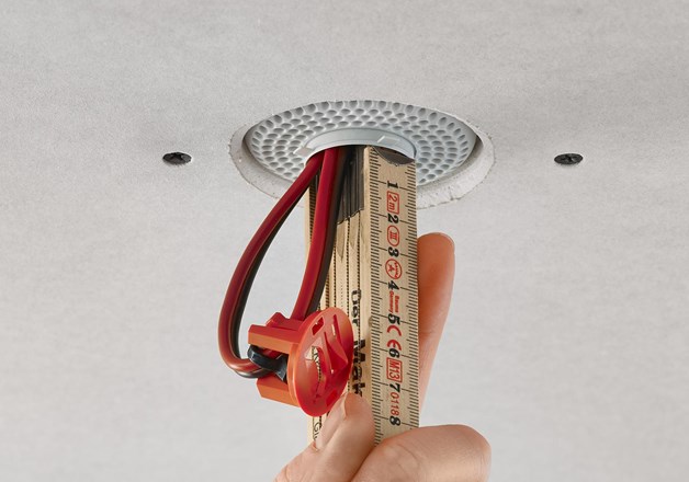
Reserve enough space for cooling element. Observe minimum installation depth for module and luminaire. If a luminaire with cooling element is used, do not cover it with insulation material, steam brake, fleece or film!
2. Run cable through opening of the filler inset. insert the module into the prepared cutout.
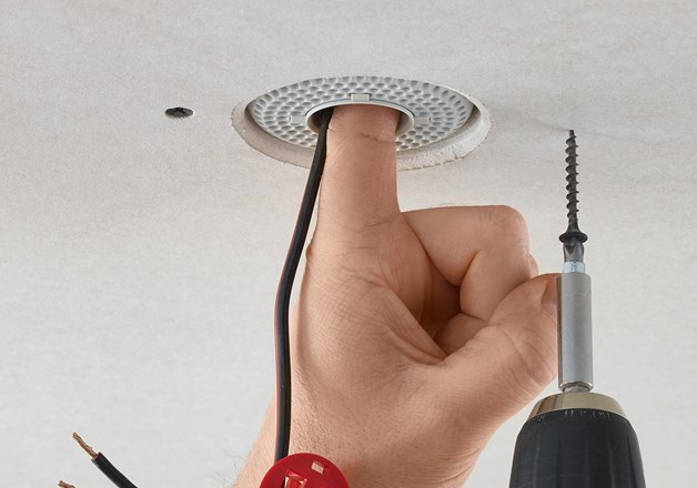
3. Insert the module into the prepared cutout and screw it into the ceiling from below. Make sure that the filler inset rests flat and clean on the plasterboard and is firmly pulled down by the screws.
4. Adjust filler ring to desired filling thickness (0-15mm). Make sure plaster claws do not stick out toward the front. Claws must be completely covered by plaster.
5. Fasten supply line to protective cover and use cover to close opening.
6. Plaster ceiling in thickness of your choice.
7. Carefully sand red protective cover until it is entirely visible.
CAUTION: Do not abrade protective cover or the plaster claws will be exposed.
8. After sanding, remove protective cover and pull cable to the front. Imprecisions have to be reworked by hand.
9. Prime and paint module and filler ring with ceiling paint.
Please check with your plasterer if you want to use coarse, loam, or acoustic plaster.
Reserve enough space for cooling element. Observe minimum installation depth for module and luminaire. See the installation instructions for the respective luminaire.
1. Prepare substructure for screwing installation module into drywall ceiling. Use screwdriver to clear openings for empty conduits in the lid and clean them. Press empty conduits
into the openings until they are fastened (about two or three corrugations).
2. Screw drywall capsule into intended opening.
3. Use filler ring to adjust filling edge to desired plaster thickness. Make sure plaster claws do not stick out to the front. Claws must be completely covered by plaster.
4. Fasten supply line to protective cover and use it to close opening. Make sure plaster claws have a solid grip in the plaster.
5. Plaster ceiling in thickness of your choice.
6. Carefully sand protective cover until it is entirely visible.
CAUTION: Do not abrade protective cover or the plaster claws will be exposed.
After sanding, remove protective cover and pull cable to the front. lmprecisions have tobe reworked by hand.
Prime and paint module and filler ring with ceiling paint.
CAUTION: Please check with your plasterer if you want to use coarse, loam, or acoustic plaster.
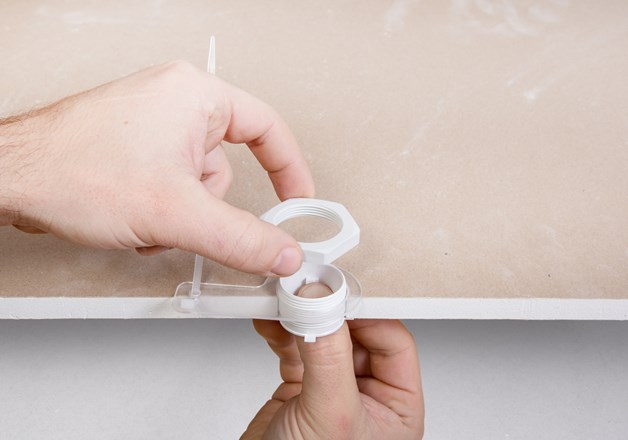
2. Drywall mounting ring into opening from below, add cable holder and fasten filler ring with screw nut from above.
CAUTION: Make sure to place plaster claws flat on drywall. Plaster claws must not protrude into space below.
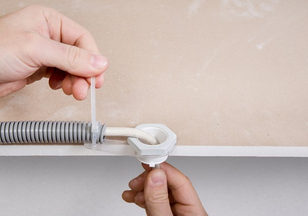
3. Secure cable to cable holder with cable tie.
4. Fasten supply line to protective cover and use the cover to close opening. Make sure plaster claws do not stick out to the front. Claws must be completely covered with filler.
5. Plaster ceiling.
6. Carefully sand protective conver until it is entirely visible.
CAUTION: Do not abrade protective cover or the plaster claws will be exposed.
After sanding, remove protective cover and pull cable to the front. Imprecisions have to be reworked by hand.
Prime and paint the filler ring with the ceiling paint. Module is not suitable for coarse plaster!
CAUTION: Please check with your plasterer if you want to use coarse, loam, or acoustic plaster. Alternatively Spackling insert 68-28 (Item No. 208862) therefore may be more suitable.
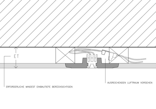
Reserve enough space for cooling element. Observe minimum installation depth for module and luminaire. If a luminaire with cooling element is used, do not cover it with insulation material, steam brake, fleece or film!
Ensure that the minimum air space for the respective luminaire is provided in the ceiling substructure.
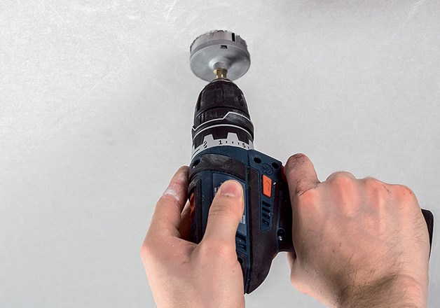
1.
Drill a perpendicular hole (e.g. drill stand or router cutter) with a diameter of 35mm. The minimum thickness of the plate must be 18mm and must not exceed 35mm for lights with heat sinks.
2.
Take the installation ring and position it flush with the lower edge of the ceiling.
3.
The wooden installation ring is secured by screwing in the two grub screws. The grub screws must be screwed in so deeply that they are countersunk into the threaded hole (approx. 1 mm).
The minimum installation depth of the installation module and luminaire must be observed. When using a luminaire with a heat sink, it must not be insulated or covered with a vapor barrier, fleece or foil!
OPTIONAL: For higher quantities we recommend the mounting aid (ArtNo. 178071).
Ensure that the minimum air space and installation depth for the respective
luminaire is available in the ceiling substructure. NOTE: The wood moisture content indoors should be max. 8–10% during drilling and installation. The clamping ring must be inserted immediately after drilling, as the diameter of the drill hole may change due to moisture changes.
1.
Drill a hole with a diameter of 30 mm at a 90° angle (e.g., using a drill stand or router). The material thickness must be between 12.5 mm and 35 mm.
2.
First, place the clamping ring 28 to the beginning of the metal barbs. If there are several clamping rings in a row, you can align them using the wings. This ensures that the mounting holes in the cover ring are aligned later on.
3.
Push the clamping ring into the hole until it reaches the depth stop on both wings. Once it is fully inserted, the clamping ring is fixed in place and can no longer be turned or adjusted.
4.
These can then be broken off by twisting them.
In the case of luminaires with heat sinks, these must not be covered with insulation, vapor barrier, fleece, or foil!
Installation
TRIM RENDEL 28, TRIM FLAT 28 und TRIM FLAT 68-28*
INSTALLATION DEPTH:
TRIM RENDEL 28: 50mm
TRIM FLAT 28: 60mm
TRIM FLAT 68-28: 60mm
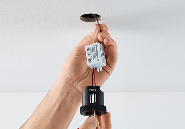
2. (OPTIONAL) If you use a mini LED-driver for a luminaire, please connect it before mounting the cavity bracket. Observe an additional air space. For the TRIM FLAT 68-28, the LED drivers 399023, 299223, 299225 and 299227 also fit through the Ø68mm hole with an installation depth of min. 120mm.
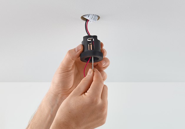
3. Insert the cavity bracket into the hole. Use a 1,5m allen key to turn thethe two fastening screws anticlockwise
until the cavity bracket is secured. To ensure that the hexagon socket of the fastening screw is not overtightened, this must be done with a little strength.
4. Now mount your component of the DOT 28 System using the bayonet lock.
Observe general information regarding installation of DOT 28 luminaires and maximum current feed: At least 1dm³ of air space must be provided for the DOT 28 and 5dm³ for the DOT 28 Power. The minimum installation depth must be observed. The luminaire must not be insulated or covered with a vapor barrier, fleece or foil!
Installation
DOT 28 +
DOT 28 POWER
Observe general information regarding electrical installation and maximum power input.
Assembly pliers required.
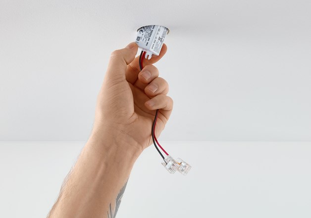
1. Connect the luminaire correctly to the feed of the LED driver (constant feed). The LED driver must be disconnected from the power supply! It is essential to ensure that the constant current source has been disconnected from the mains for at least 10-15 seconds before lights are connected!
2. We recommend using the circlip pliers 10-25mm (art. no.: 168101) to mount the light in the best
possible way. Before inserting the light into the installation module, make sure that the hole is free of dirt. Insert the working tips into the mounting holes and press the circlip pliers together with a firm grip. Insert the light into the installation module as far as it will go and carefully turn it 90° to the right. Once back at the stop, pull the light downwards until it is flush with the ceiling. When installing the light completely, make sure that the circlip pliers are held firmly to prevent slipping and possible damage to the cover ring.
To de-install, hold the light with the circlip pliers again with a firm grip and push it into the ceiling as far as it will go. Turn the light 90° to the left and carefully pull it downwards and out of the
ceiling.
CAUTION: Provide enough airspace for the cooling element. Observe minimum installation depth. Do not cover with insulation material, steam brake, fleece or film!
For DOT 28 CONE and DOT 28 POWER CONE, the luminaire is always supplied with an integrated lifting bracket.This is used to pull the luminaire up to the ceiling.
Installation
WALL 28 +
WALL 28 POWER
Not available with DIM TO WARM and LENS 15° technology.
Use DOT SLIM technology for higher power rangers.
1. Ensure that the installation module is installed correctly in
accordance with the instructions. Inaccurate installation can lead
to grazing light images. Ensure that the bayonet ring is flush with
the heat sink. Figure 1 red marking. To install the light correctly, the
exact sequence of steps must be followed.
2. Connect the light in series
correctly to the supply line of the corresponding LED driver. The LED
driver must be disconnected from the mains voltage. Ensure that the
LED driver has been disconnected from the mains for at least 10-15
seconds immediately before connecting the luminaire.
3. Take the locking pliers and insert the light into the bayonet
mount up to the stop (A). Turn the light clockwise (approx. 340°)
with slight upward pressure until the light reaches the end stop (B).
It must be possible to do this smoothly and without great effort.
4. Pull the light
downwards at the end stop (C) until it is flush with the ceiling. This
ensures that the luminaire is correctly seated in the bayonet mount.
When flush and with a slight downward pull, you can now align the
luminaire/reflector to the wall (D). This adjustment must also be
possible without great effort.
Use flexible supply cables (e.g. low-voltage cables) to avoid transferring tensile stresses to the luminaire.
CAUTION:
For thermal reasons, installation in the wooden capsule does not work.
Due to a sharp edge on the internal thread of the WOODEN INSTALLATION RING, the WALL28 or WALL28 POWER can only be installed in WOODEN INSTALLATION RINGS that were delivered from March 1st, 2024. WOODEN INSTALLATION RINGS delivered
before this date can be deburred when installed by hand, using a circular grinder or sandpaper.
Precise installation of the built-in module is required due to the grazing light.
Installation SFERE 28
MAX. CURRENT:
Installation heights lower than 230cm: 250mA
Installation heights over 230cm: 350mA
For wall-installation, use SFERE 28 with additional bayonet mounting for wall installation (ArtNr. 278505).
1. Connect the
luminaire correctly to the feed of the led-driver (constant feed,
max. 350mA if installation height is over 230cm). The led-driver
must be disconnected from the power supply!
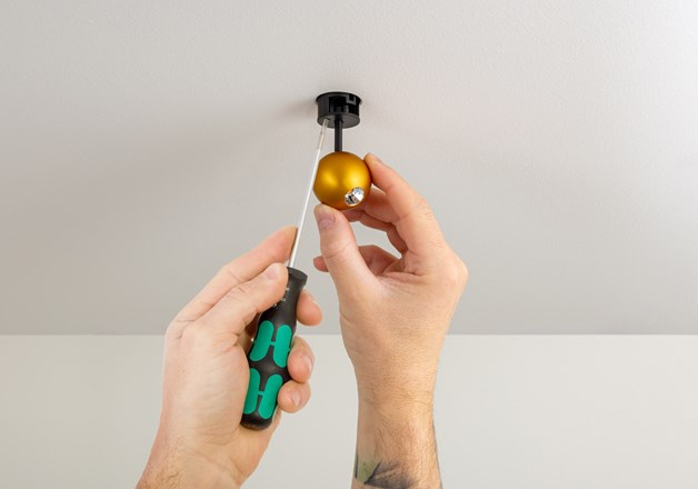
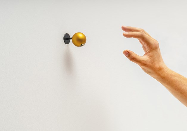
2. Insert the luminaire
into the bayonet mechanism of the ceiling outlet. Carefully
rotate SFERE 28 by 90° to the right and pull down until the
mounting sits flush with the ceiling.
For different orientation, rotate SFERE 28 by 180° before inserting it into the
bayonet mechanism.
To de-install, lift SFERE 28 and rotate counter-clockwise by 90°.
For wall-installation, use SFERE 28 with additional bayonet mounting for wall installation (ArtNr. 278505).
Installation
CERA 28 +
CERA C 28
Observe general information regarding electrical installation
and maximum power input.
Recommendet current feed for size S as mirror luminaire : 250mA
1. Connect the luminaire correctly to the feed of the
led-driver (series circuit, max. 350mA). The led-driver must be
disconnected from the power supply!
2. Insert the luminaire into the bayonet mechanism of the ceiling
outlet. Carefully rotate CERA 28 by 90° to the right and pull down
until the mounting sits flush with the ceiling.
OPTION WALL INSTALLATION:
For wall-installation the supplied rubber bullets can be
pressed into the prepared holes in the cooling element.
To de-install, lift CERA 28 and rotate
counter-clockwise by 90°.
CAUTION: Separate from power supply at least 10 –15 seconds before installation.
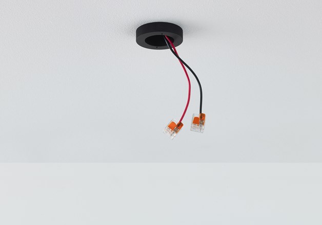
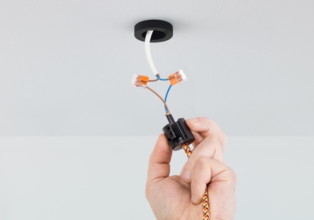
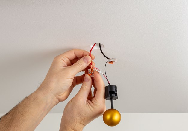
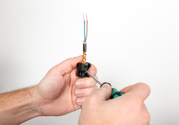
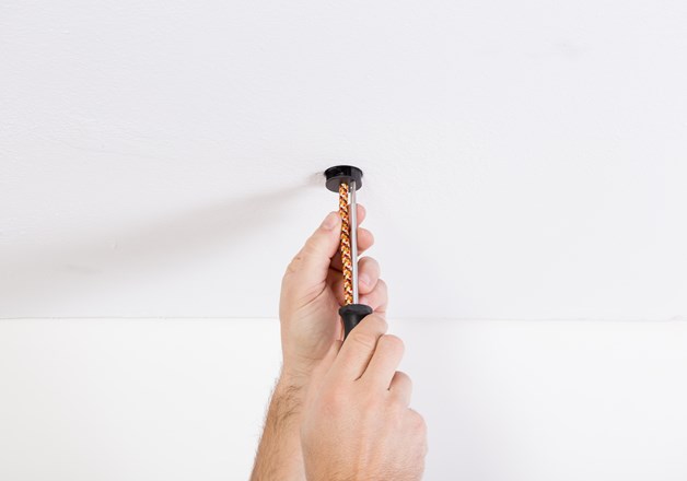
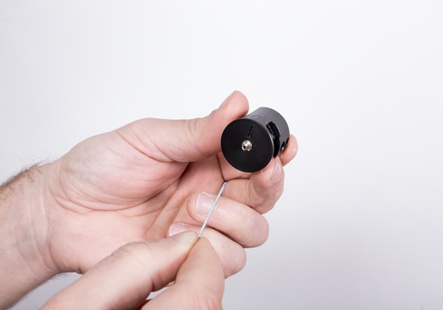
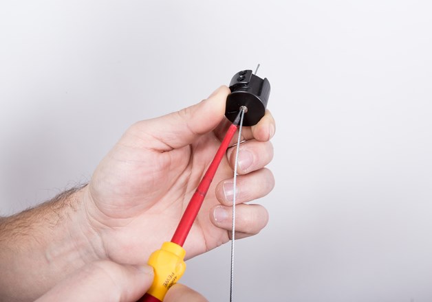
1. Adjust and carefully secure cable length using the two socket screws. Install pendant luminaire according to the installation manual enclosed.
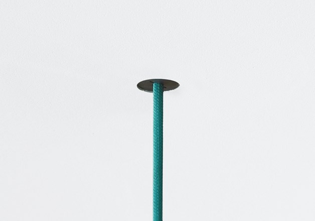
Push bayonet mechanism up with slotted
screwdriver and rotate clockwise by 90°, then pull downwards
until it locks into place.
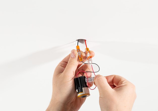
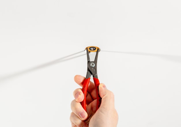
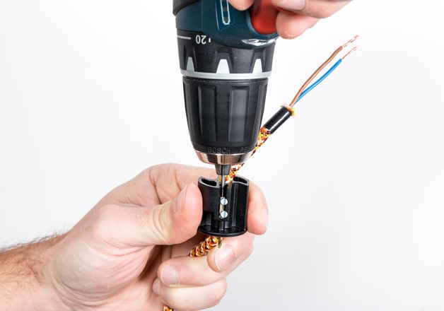
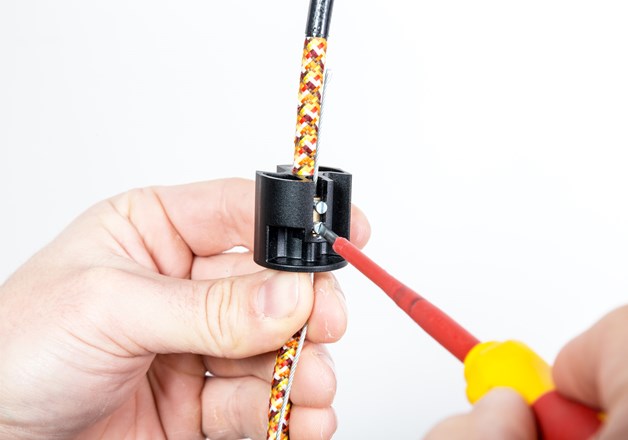
2. After setting the right length, use enclosed blade and carefully open side of protective tube.
3. Cut protective tube just below bayonet mechanism.
4. Carefully remove protective tube from cable.
CAUTION: Mesh cable is under low voltage and must not touch any metal
elements below or within the ceiling.
HOT PLUG DANGER! Separate from power supply at least 10 –15 seconds before installation.
Installation BALDA 28
MAXIMUM LOAD 1 TO 10 KG, DEPENDING ON CABLE AND MODULE
2.Connect the luminaire correctly to the feed of the LED driver (constant feed). The led-driver must be disconnected from the power supply! It is essential to ensure that the constant current source has been disconnected from the mains for at least 10-15 seconds before lights are onnected.
3. Push the springs attached to the
lighting module back and insert the luminaire into the opening provided.
CAUTION: Provide enough airspace for the cooling element. Observe minimum installation depth. Do not cover with insulation material, steam brake, fleece or film!
Installation also applies to DOT 35 and DOT 35 POWER with glare supression, fade ring or CONE.


.jpg?size=628x440&v=pgLZE0G31ssfQ2Ry%2BJqY7gNxgfA%3D)

.jpg?size=53x37&v=pgLZE0G31ssfQ2Ry%2BJqY7gNxgfA%3D)


.jpg?size=628x440&v=qu%2BPsvqjqShGn6GKhnx5%2Fn8m%2Fks%3D)
.jpg?size=628x440&v=GeH4h22oer%2Fcw37uTC38V4s1JnI%3D)
.jpg?size=628x440&v=PkmhVwVRYkbY67w1lIn7lGS6zwY%3D)
.jpg?size=628x440&v=qwWJhZ4cxht1KdX2%2FyAmwOLY9Jg%3D)
.jpg?size=53x37&v=qu%2BPsvqjqShGn6GKhnx5%2Fn8m%2Fks%3D)
.jpg?size=53x37&v=GeH4h22oer%2Fcw37uTC38V4s1JnI%3D)
.jpg?size=53x37&v=PkmhVwVRYkbY67w1lIn7lGS6zwY%3D)
.jpg?size=53x37&v=qwWJhZ4cxht1KdX2%2FyAmwOLY9Jg%3D)


.jpg?size=628x440&v=kbgqpX%2BiSoWI23TBZdb6sIRfN6g%3D)

.jpg?size=53x37&v=kbgqpX%2BiSoWI23TBZdb6sIRfN6g%3D)


.jpg?size=628x440&v=saFGQCX68w%2F1CF47hd%2FJUMunVz0%3D)
.jpg?size=628x440&v=1F76Cwg7UYNuMvBQuRmAH0dIrCE%3D)


.jpg?size=53x37&v=saFGQCX68w%2F1CF47hd%2FJUMunVz0%3D)


.jpg?size=53x37&v=1F76Cwg7UYNuMvBQuRmAH0dIrCE%3D)